- NOVUM
- Simulators
| Our primary software products are CNC simulators, we have developed almost 100 in the recent years. The use of simulators is a reasonable choice in case of individual production of expensive parts on high-cost machines, but they can also be used for small and medium batch production on smaller and simpler machine tools. The mistake is an inevitable consequence of technologist work, and it can lead to serious damage, waste, tool breakage, loss of production, deadline delay and penalty. |
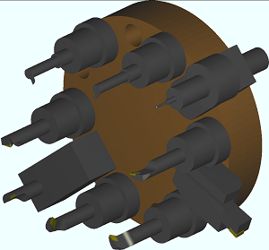
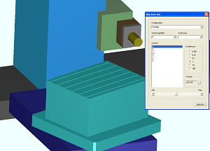
Realistic modelling
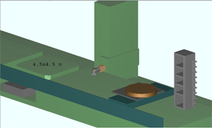
of all axes, assemblies, attachments and tools of the given machine tool. The working area of the machine tools ranges from one hundred mm up to 44 meters, see below, the number of axes from 2 up to dozens.
Syntactic and semantic check
of NC programs. Our simulators are able to understand the complete instruction set of most common advanced CNC controls, but we also undertake unique simulator developement for other CNC controls.
CNC format - 1
NO96O L111 R111=9O
()
NO965 GI6 W U2= W
NO97O GO GSS G64 D68l XO YO
NO97S GS8 W-500 V500
NO980 GO W100 V0
()
NO98S GO U2=330
NO990 GO W10
NO99S L2lO R6OO=27O ( WERKZEUGABGLEICH: W=10MM )
()
N1000 GO U2=300 M3
()
R20 = 41 ( UNTERPROGRAMNUMBER )
R21 = 314.52 ( STARTPUNKT DER U-ACHSE )
R22= 0 ( STARTPUNKT DER W-ACHSE )
R24= 0.50 ( SCHLICHTZUGA8E U-ACHSE )
R25= 0.05 ( SCHLICHTZUGA8E W-ACHSE )
M0
CNC format - 2
N1000 PROC HEADCH (STRING[20] WZ_BEZEICHNER)
;Definieren lokale Variablen ----------------------------------------
N1005 DEF INT MTHNR, TNR_EIN, TNR_ZWSP1, TNR_ZWSP4, TNR_ZWSP8
N1010 DEF INT TNR_MAGPL, KOPFNR_EIN, KOPFNR_ZWSP4, KOPFNR_ZWSP8
N1015 DEF INT PU_AKTION
N1020 DEF INT MVT_STATUS
;Abfrage Simulation/Probelaufvorschub:-------------------------------
N1025 IF $P_SIM GOTOF ENDE ;Abfrage Simulation
N1030 IF NOT $P_SEARCH ;Kein Satzvorlauf
N1035 WHILE $P_DRYRUN ;Abfrage Probelaufvorschub
N1040 MESSAGE("ALG_001") ;Probelaufvorschub abwńhlen
CNC format - 3
N64 #3=#1+#4
N66 #5=[#4-#8]/#2
N68 #6=FUP [#5]
N70 #7=[#4-#8]/#6
N72 G00 Z#3
N74 WHILE [#6 NE 0] DO1
N76 G91 G01 Z-#7
N78 G90 G1 Y-300
N80 G00 X-450
N82 G00 Y290
N84 X-705
N86 G01 Y-300
N88 G00 X-450
N90 Y290
N92 X-600
N94 #6=#6-1
N96 END1
N98 G00 Z800
N100
N102 G0 X600 Y290
N104 #1=520 (KESZ MERET)
N106 #2=5 (FOGASMELYSEG)
N108 #4=20 (ONTESI RAHAGYAS)
CNC format - 4
N1
( Vertical head Sk60 )
G58 X0 Y0 W0
G16 XYW
@100 K9999
N2 ( No.2 )
( Uni-Hirth Kopf )
( )
@121 R912 K0 K100
G16 X Y W
@111 R914 K0 K50
K90 K40
K180 K30
K270 K20
@100 K10
( )
N10 @630 R23 R914
@631 R24 R914
R30= R101 * R24
R29= R101 * R23
R27= R102+R103
G16 XYW
G58 X=- R30 Y=- R29 W=R27
CNC format - 5
%
N1 T579760 T325000 T0 T0
N3 T579660 T442610 T0 T0
N4 T635640 T357800 T0 T0
N5 T651800 T356450 T0 T0
N6 T580420 T452650 T0 T0
N8 T596400 T402860 T0 T0
N13 T651800 T356450 T0 T0
N16 T596400 T398960 T0 T0
N34 M02
%
L1000
N3000 G01 X0 +R1 F60 (BESZURAS)
N3100 X0 +R2 F4000
N3200 G91 Z2500
N3210 Z500 F500
N3300 G90 M17
L0500
N5000 G01 G91 X5000 F4000
N5010 G90 Z-84500 F220
N5020 G91 X-1000
N5030 G00 G90 Z8000
N5040 M17
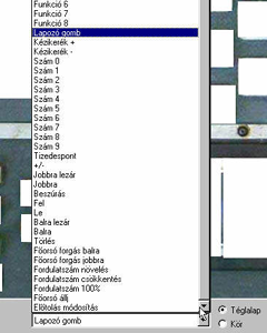
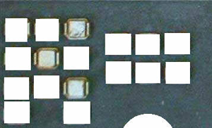
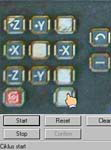
The user interface
may be overlapped with the photo of the given CNC control, so the technologist can feel in a completely realistic environment.
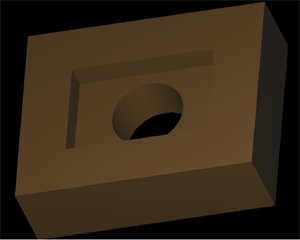
Definition of simple solids
(block, prism, sphere) and creating the result of Boolean operations between them.
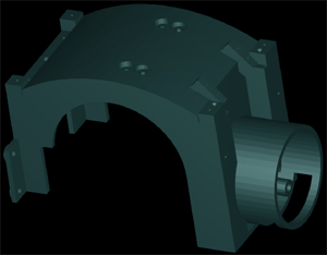
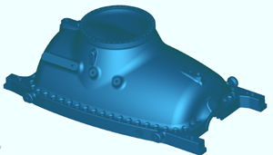
Importing solid
of the model of the raw or finished part in one of the standard CAD formats. Locating the part int he working area of the machine tool together with fixture elements.
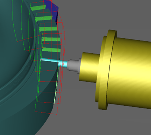
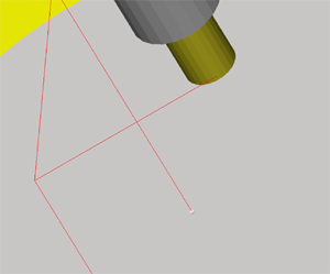
Realistic simulation
of the cutting process on the solid model of the part and/or visualization of the tool path.

Wide range of turning and milling tools
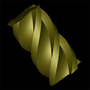
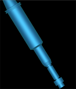
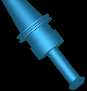
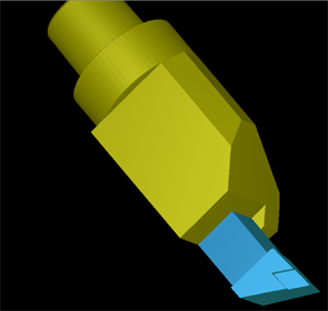
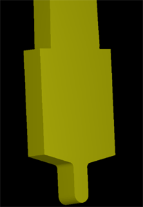
can be simulated i.e cylindrical, conical, spherical, toroidal, slittingsaw and profile-milling cutter. Tool models from tool manufacturers can directly be imported.


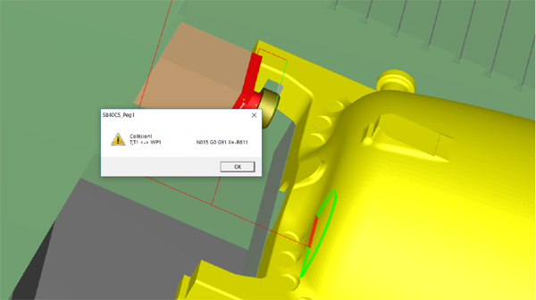
Complete collision check
It is often the case, that in case of a complex machining head, only a few millimeters distinguish between good machining and collision, the software always gives a correct evaluation. At feedrate only the allowed cutting part of the tool can touch the part, nothing else can get together. At rapid traverse all overlappings are prohibited. This collision was caused intentionally by wrong zero point setting.
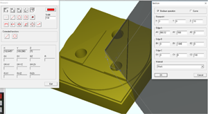
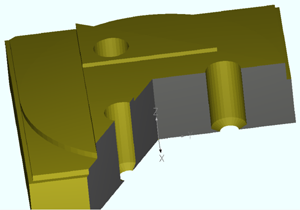
Measuring
during or after manufacturing. It can be used for checking the zero point setting, the tool correction, for checking the position and distance of machined planes, the position and depth os holes. Dimensioning according to measured values. Cross-sectioning of the solid model.

Projects
All information about a given working task (part model, NC program references, zero offsets, tools, dimensioning ) are stored in projets.


